(home)
(Full Firmware Plan)

Peak Search (PS)

(Firmware coder: Jon Wilson)

Structure

The Peak Search (PS) module consists of 4 submodules which compute the trigger primitives that are eventually written into the L1 Trigger FIFO. Each submodule searches for the peak of the corresponding trigger waveform produced by the corresponding Finite Impulse Response (FIR) submodule. It records the peak amplitude of the trigger waveform, the timestamp when the peak occurred, and constructs a "trigger word". The trigger word records the state of the 8 threshold bits (from the Threshold Logic (ThL) module) at the peak and in the vicinity of the peak. (More details about how this trigger word is defined, as well as the precise definition of the "vicinity of the peak", are found in the Brief Functional Description section of this page.) The trigger word is used by the Trigger Logic (TrL) module to make the L1 trigger decision. Eventually, depending on the L1 trigger decision, the peak amplitude, peak timestamp, and trigger word will be stored into the L1 Trigger FIFO. This provides the L2 trigger with the information necessary to make the L2 trigger decision and to correctly position the readout window around the peak.

The input to the PS module is a five-word packet received from the ThL module. The first four words are the trigger waveform samples from each of the four FIR submodules, and the fifth word indicates which of the 8 thresholds (in the ThL module) are exceeded at this moment.

The output of the PS module is a set of trigger primitives: the peak amplitude, the peak timestamp, and the trigger word. The output is sent to the TrL module to make the L1 trigger decision. In contrast to most other modules in the L1 firmware, which produce one output packet every time they receive an input packet, the PS module only produces output intermittently. Each submodule produces a single output when the "peak search window" (defined below) ends.

All 4 PS submodules work in parallel. The code for each is identical, but the inputs, and therefore the outputs, may differ.

Data Inputs There is 1 streaming input, from the Threshold Logic module.
  • The input contains the following information:
    • Trigger waveforms 1-4
    • Discriminator decisions (8 bits), also called "threshold logic bits" and notated \(t_i\)
  • The input is formatted as a 5-channel packetized Avalon-ST stream.
    • The input stream includes the following signals (see table 5-1 of the Avalon-ST specification for detailed descriptions of the signal roles):
      • 16 bit wide data signal (which is used to carry the 5 inputs in serial)
      • 3 bit wide channel-number signal (to specify which of the 5 channels each datum belongs to)
      • 1 bit wide valid signal
      • 1 bit wide start-of-packet signal
      • 1 bit wide end-of-packet signal
    • Packets will be received at a rate of 39.0625 kHz.
    • Note: The four trigger waveform samples are carried on channels 0-3, and the ThL module's 8 bit output is carried on channel 4. That is, when receiving the trigger waveform sample produced by FIR 0 (and passed through the ThL module unaltered), the channel-number bits will be 000. When receiving the trigger waveform sample produced by FIR 4, the channel-number bits will be 011. When receiving the 8 bits produced by the ThL module, the channel-number bits will be 100.
    • Each packet will contain exactly one sample from each of the 4 trigger waveforms as well as exactly one 8-bit ThL module output.
    • The 8-bit ThL module output, carried on channel 4, is zero-padded. Since the data signal is 16 bits wide, the 8 most-significant bits will all be set to zeros while the 8 least-significant bits will be set to the 8 bits produced by the ThL module.
Configuration and Control Inputs
  • Threshold Logic Selectors $S_i$: 2 bits / Selector, 1 Selector / ThL submodule, 8 ThL submodules
    (these are used to construct the peak-search window correctly -- see details below)
  • Max window length $t_\text{max}$: 16 bits / register, 1 register / PS submodule, 4 PS submodules
    (maximum length of peak search window -- used to identify pulses which saturate the TESs for special handling)
  • Saturated-pulse timestamp offset $\Delta t_\text{sat}$: 16 bits / register, 1 register / PS submodule, 4 PS submodules
    (used to help calculate the reported peak timestamp for saturated pulses)
  • Current timestamp: 32 bits
    (This is a counter that is incremented in the DCRC firmware every time a phonon ADC sample is stored into memory. It is set to zero at the beginning of a series, and so it records the number of phonon samples recorded since the series start. It will roll over to zero about every 2 hours, which is more than long enough to avoid any ambiguity for the MIDAS front-end.)
  • 100 MHz clock input
  • 1 reset input

Note that the Selectors, Max window length, and saturated-pulse timestamp offset are set during initialization1 at the start of running and are expected to remain the same after that, but they can be changed at any time if needed.

Output There is 1 streaming output, which goes to the Trigger Logic (TrL) module.
  • The output contains the following information:
    • peak timestamp
    • peak amplitude
    • trigger word
  • The output is formatted as a 4-channel Avalon-ST stream, and does not use packets unlike other Avalon-ST interfaces used in the L1 trigger firmware.
    • The output stream includes the following signals (see table 5-1 of the Avalon-ST specification for detailed descriptions of the signal roles):
      • 64 bit wide data signal, broken down as follows, ordered from the most-significant bits to the least-significant bits:
        • peak timestamp: 32 bits
        • peak amplitude: 16 bits
        • trigger word: 16 bits
      • 2 bit wide channel-number signal (to indicate which of the 4 submodules produced each output)
      • 1 bit wide valid signal
    • Note that, in contrast with other Avalon-ST interfaces used in the L1 trigger firmware, this interface does not use packets. The valid signal is used to indicate when an output is being sent. Since each submodule uses an independent peak-search window and produces an output only when its peak-search window closes. The submodules do not produce outputs together. Each output is independent of the others.
    • The channel-number signal is used to indicate which of the 4 submodules produced each output. That is, when PS 1 produces an output, the channel-number bits will be set to 00. When PS 4 produces an output, the channel-number bits will be set to 11.
    • Note that the trigger word is, as shown in Table 1, composed of an 8-bit "at-peak trigger word" and an 8-bit "during-window trigger word". The "at-peak trigger word" is found in the most-significant 8 bits of the 16-bit trigger word, and the "during-window trigger word" is found in the least-significant 8 bits of the 16-bit trigger word.
Internal Registers This module requires some information to be retained from one time step to the next. It will be stored in the following internal registers. These registers are not visible or accessible from outside the module. They are mentioned and named here in order to simplify the detailed description of the module's functionality given below.
  • Maximum trigger waveform amplitude $A_\text{peak}$: 16 bits / register, 1 register / submodule, 4 submodules
    (stores the maximum trigger waveform amplitude during the peak search window, used to compute the peak amplitude)
  • Timestamp at peak $t_\text{peak}$: 32 bits / register, 1 register / submodule, 4 submodules
    (stores the timestamp of the maximum trigger waveform amplitude, used to compute the peak timestamp)
  • Timestamp at peak search window start $t_0$: 32 bits / register, 1 register / submodule, 4 submodules
    (stores the time at which the peak search window began)
  • At-peak trigger word: 8 bits / register, 1 register / submodule, 4 submodules
    (stores the Threshold Logic output values at the moment of the peak trigger waveform amplitude)
  • During-window trigger word: 8 bits / register, 1 register / submodule, 4 submodules
    (stores whether each Threshold Logic output value was true at any moment during the entire peak search window)
  • Current peak search window state: 1 bit / register, 1 register / submodule, 4 submodules
    (stores whether we were previously inside or outside the peak search window)
  • Current input: 16 bits / register, 1 register / submodule, 4 submodules
    (stores the most-recently received trigger waveform input value until we are ready to process it)
  • Threshold logic bits: 8 bits / register, 1 register / submodule, 4 submodules
    (stores the most-recently received Threshold Logic bits until we are ready to process them)
Error bits

The module detects and reports several possible erroneous conditions via a register read. The value read out consists of 16 bits; the most-significant bits are unused.

  • Bit 0: Received data outside of a packet
  • Bit 1: Received start-of-packet signal during a packet
  • Bit 2: Received end-of-packet signal outside of a packet
  • Bit 3: Duplicated channel in a packet
  • Bit 4: Missing channel in a packet
  • Bit 5: Illegal channel number in input
  • Bit 6: Read or write to invalid register address
  • Bit 7: Invalid value written to register
  • Bit 8: Input packets arrived too close together
  • Bit 9: Output packets collided
Functionality Brief functional description:

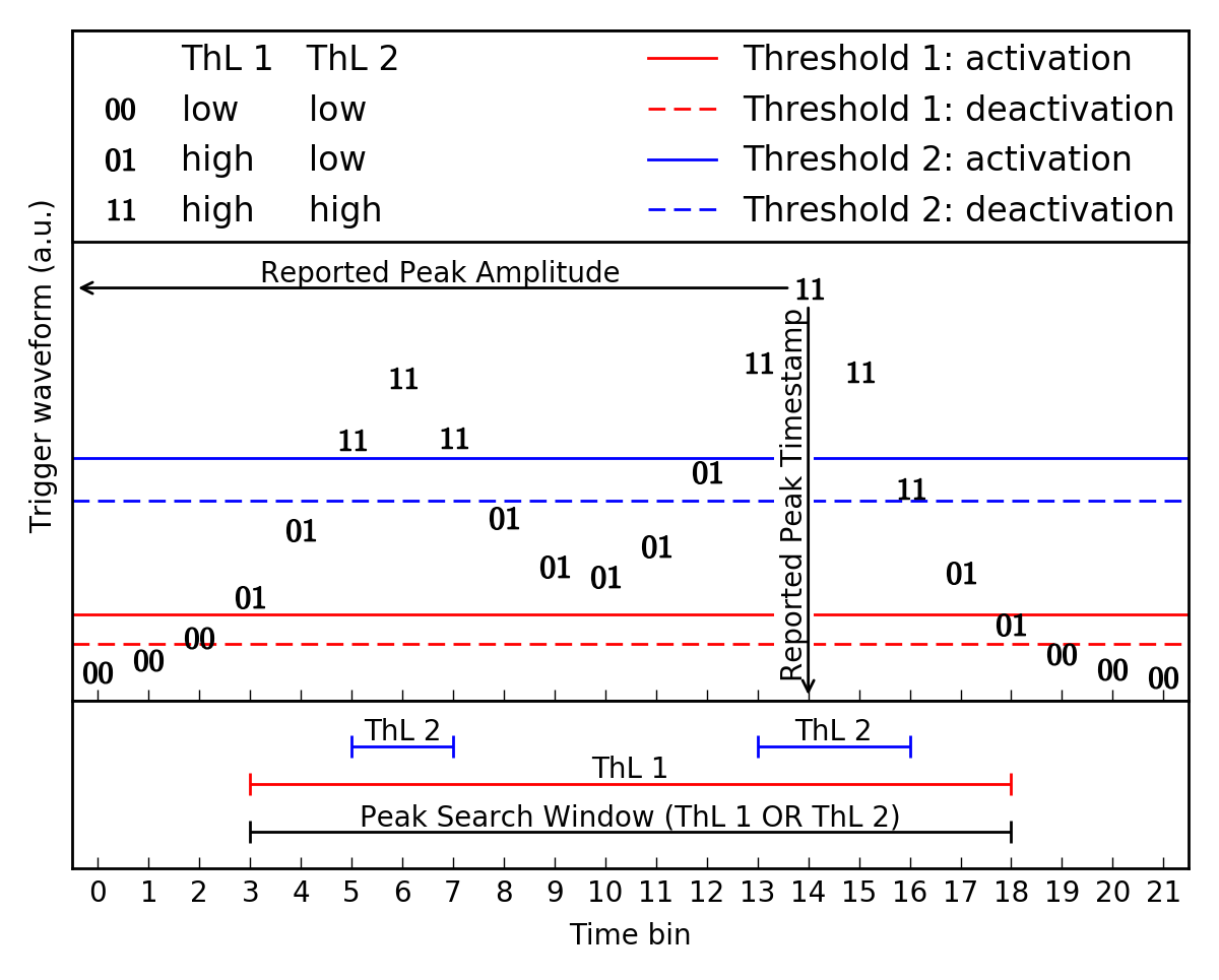
Each PS submodule does a number of things. It defines a "peak search window", which will be used to construct a set of "trigger primitives". The trigger primitives consist of the peak amplitude and peak timestamp of the input trigger waveform as well as a "trigger word" that contains the state of all 8 input threshold logic bits during the peak search window and at the trigger waveform peak. It also handles "saturated pulses", which are a difficult but frequent occurence. Finally, the trigger primitives are sent on to the TrL module, which makes the final L1 trigger decision.

Figure 1 shows an example trigger waveform input (the same as used in Figure 1 on the ThL module design page) from FIR submodule 0. We will use and expand on this example through the rest of this page. In this example, we assume that ThL Selectors 1 and 2 are set to 0 (associated with FIR submodule 0) while all the other ThL Selectors are set to other values. This figure shows, in this example, how the peak search window is defined from the input threshold logic bits ThL 1 and ThL 2.

PS Window 1

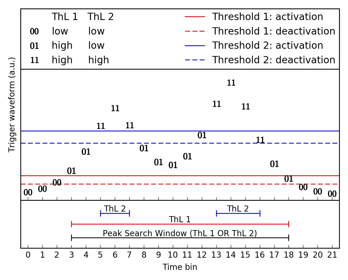
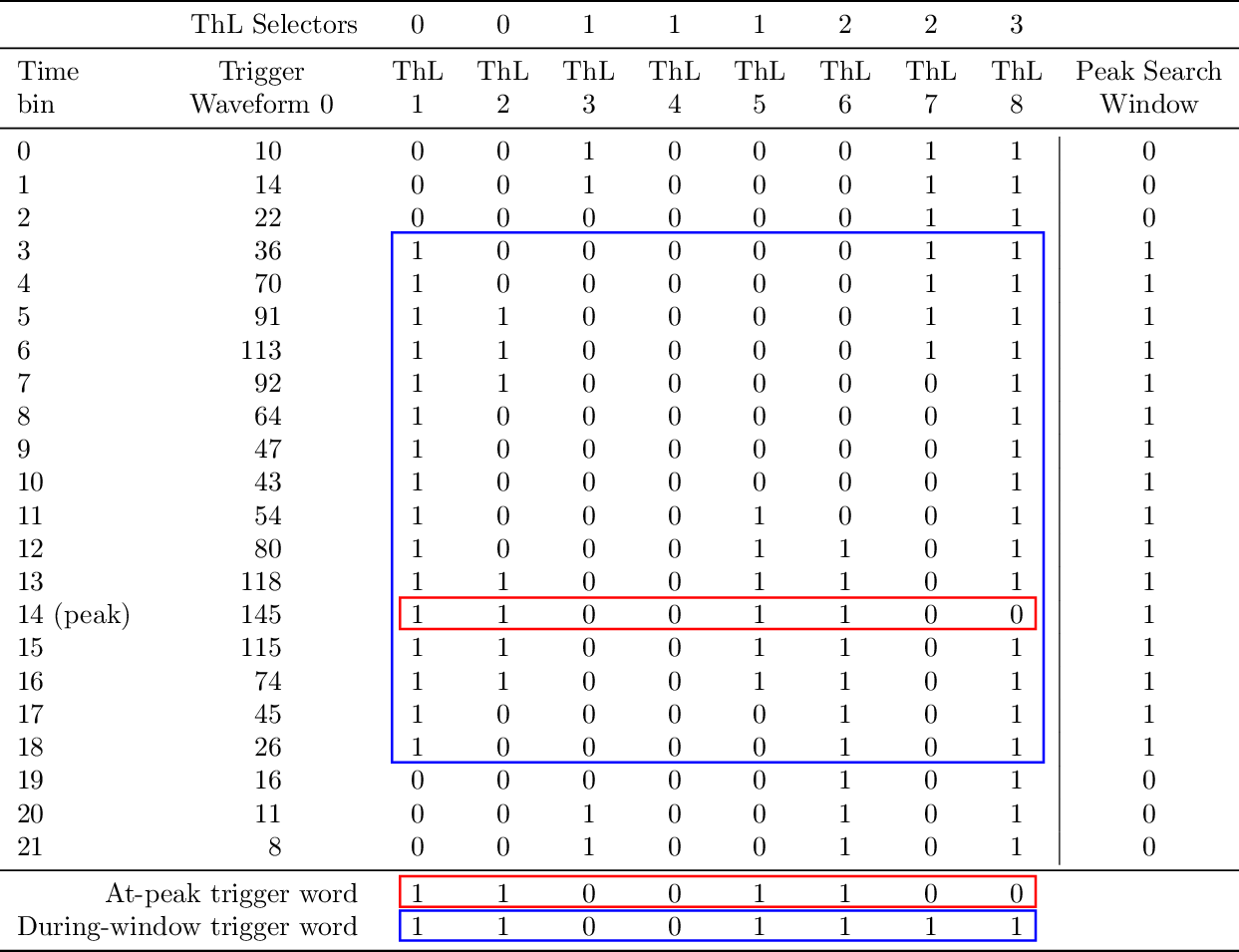
Figure 1: This figure shows the same input as used in the ThL design page with a pileup event for FIR 0. In this case only ThL 1 and ThL 2 are used for this trigger waveform. Note that the activation and deactivation lines are not used directly in the PS module, only the values of the ThL 1 and ThL 2 results, and the value of the trigger waveform which contains the information needed.

Peak Search Window definition

The peak search window is the time during which the trigger waveform is above the lowest of the associated thresholds described in the ThL module, where said association is defined by the Threshold Logic Selectors.

In a little more detail, the Peak Search Window is defined using the 8 ThL bits received from the ThL module as well as the Threshold Logic Selectors described in the Configuration and Control Inputs. That is, for peak search submodule \(n\), Threshold Logic Selectors \(s_i\), and ThL bits \(t_i\), the peak search window is any contiguous block of time in which the following "peak search window bit" is TRUE: \[\operatorname*{OR}_{i=0}^{7} ((s_i == n) \operatorname{AND} t_i),\] where \(\operatorname*{OR}_{i=0}^{7}\) is the logical OR of all eight terms, and \(\operatorname{AND}\) is the logical AND operator. The peak search window begins when this expression becomes TRUE, and ends again when it becomes FALSE once again. Note that the "$t_0$" internal register will be set to the current timestamp at the moment the peak search window begins.

Although the peak search window is not reported in the output, it is used to define the trigger primitives (peak amplitude, peak timestamp, and trigger word), which are described in the next section.

Continuing the example from Figure 1, we assume that ThL Selectors 1 and 2 are set to this FIR input while all the other ThL Selectors are set to other FIR inputs. That is, this trigger waveform has only the two thresholds (and corresponding ThL bits) shown in Figure 1. Then, the peak search window for this submodule is defined by the logical OR of both of the two ThL bits. In Figure 1, ThL 2 has the value 1 during time bins 5-7 and again during time bins 13-16, and ThL 1 has the value 1 during time bins 3-18, and so the peak search window in this example extends from time bin 3 to time bin 18, inclusive.

Construction of the trigger primitives

A set of trigger primitives consists of the peak amplitude, peak timestamp, and the trigger word, which records the status of the threshold logic bits during the peak search window and at the trigger waveform peak.

Each PS submodule searches for the peak amplitude within its peak search window. It records the peak amplitude and the timestamp at which that peak amplitude occurred. These pieces of information for our example are shown in Figure 2 and Table 1. In our example, the peak amplitude is 145 and the peak timestamp is 14.

Each submodule also constructs the trigger word based on the input threshold logic bits. The first 8 bits of the trigger word are just the values of the 8 threshold logic bits at the time of the peak. The second 8 bits of the trigger word indicate whether each threshold was exceeded at any time during the peak search window. More precise details of how each of these pieces of information is constructed are given below in the step-by-step description.

Table 1 makes explicit, in our example, exactly how the trigger word is constructed. Note that, although the peak search window is defined only by ThL 1 and ThL 2 (due to the values of the threshold logic Selectors), all of the threshold logic bits play a role in determining the trigger word. In particular, ThL 1, 2, 5, and 6 are all 1 at the peak, in time bin 14, and so the first 8 bits of the trigger word are 11001100. Additionally, ThL 7 and 8 are both 1 at some point during the peak search window, while ThL 3 is only 1 outside the peak search window and ThL 4 is never 1 at all. So, the second 8 bits of the trigger word are 11001111.

PS Window 2

Figure 2

Table 1

Once the peak search window ends, the peak amplitude, peak time, and trigger word are sent to the TrL module, which makes the L1 trigger decision and sends everything on to the L1 FIFO.

Handling of saturated pulses

Some scattering events in our detectors are energetic enough that the transition edge sensors become fully normal conducting and remain so for some time. This produces a pulse that has a markedly different shape than lower-energy pulses, a "saturated pulse". The effect, from the trigger perspective, is that the trigger waveform will rise up to some maximum amplitude and then remain there, nearly flat, for an extended length of time.

Such a flat-topped trigger waveform does not have a unique peak. The actual maximum amplitude will occur at some random point on this flat top (determined by the noise and the fine details of the pulse shape) rather than at the beginning of the flat top. Because of this, the "peak timestamp" reported by the PS module is unlikely be aligned in a consistent fashion with the rising edge of the pulse. This means that the L2 trigger will not be able to correctly align the readout window with the rising edge of the pulse. Luckily, for such a high-amplitude pulse, the time between the beginning of the peak search window (when the trigger waveform first rises above the lowest threshold) and the timestamp needed for correctly placing the readout window is more or less constant.

In order to properly handle this case, the PS submodules have two additional configuration inputs. The first is a maximum length \(t_\text{max}\) for the peak search window. If the window is below this maximum length, then the pulse is treated as a normal pulse, but if the window is longer than \(t_\text{max}\) then the pulse is treated as a saturated pulse.

The second configuration input is a timestamp offset \(\Delta t_\text{sat}\). When a saturated pulse is detected, then this offset \(\Delta t_\text{sat}\) is added to the timestamp at the beginning of the peak search window \(t_0\), and that sum, \(\Delta t_\text{sat} + t_0\) is the reported peak timestamp in place of the timestamp of the actual peak.

To sum up, \(t_\text{max}\) is used to identify saturated pulses, and \(\Delta t_\text{sat}\) is used, along with the value in the \(t_0\) internal register, to report a useful timestamp in the case of saturated pulses. Note: there is no explicit identification of saturated pulses in the trigger primitives, although the reported peak amplitude will be very large for saturated pulses.

More detailed description (including data transfer information):

Step-by-step:

This describes the functionality of one PS submodule. All 4 PS submodules work identically and in parallel.
  1. Wait for an input packet to arrive from the Threshold Logic module.
  2. When a single datum (part of an input packet) is arriving, check the channel number
    • If the channel number matches this PS submodule's index \(n\), then store the datum into the "current input" internal register
    • If the channel number is 4, then store the least-significant 8 bits of the datum into the "threshold logic bits" internal register
    • Otherwise, ignore the datum, as it is intended for a different PS submodule
  3. Unless the end-of-packet signal is received, return to step 2 and continue waiting for the rest of the input packet.
  4. Once the packet is finished (end-of-packet signal received), then compute the peak search window bit (the same as defined above in the "Peak Search Window definition" section): \[\operatorname*{OR}_{i=0}^{7} ((s_i == n) \operatorname{AND} t_i),\] where \(\operatorname*{OR}_{i=0}^{7}\) is the logical OR of all eight terms, and \(\operatorname{AND}\) is the logical AND operator.
  5. Test the peak search window bit and the "current peak search window state" internal register bit. Since there are two bits, there are four possibilities, and we will do one of four things. In three of the cases, we will move to one of the subheadings below and perform the steps listed there. The four possibilities and four actions to take are:
    • If the peak search window bit and the "current peak search window state" internal register bit are both FALSE, then take no further action, and return to step 1. In this case, we have not been in a peak search window and are not starting a peak search window.
    • If the peak search window bit is TRUE while the "current peak search window state" internal register bit is FALSE, then set the "current peak search window state" internal register bit to TRUE and perform the steps listed under "start of peak search window steps" below. In this case, we have not been in a peak search window, but now we are starting a peak search window.
    • If the peak search window bit and the "current peak search window state" internal register bit are both TRUE, then perform the steps listed under "during peak search window steps" below. In this case, we have been in a peak search window, and we are remaining in that peak search window.
    • If the peak search window bit is FALSE while the "current peak search window state" internal register bit is TRUE, then set the "current peak search window state" internal register bit to FALSE and perform the steps listed under "end of peak search window steps" below. In this case, we have been in a peak search window, but now the peak search window is ending. Since no more information from the inputs is needed to finalize the trigger primitives, the "end of peak search window steps" finalize the trigger primitives and send them to the TrL module, which makes the final L1 trigger decision.
  6. Return to step 1 and wait for the next input packet.

Start of peak search window steps:

  1. Set the "maximum trigger waveform amplitude" internal register to the value of the "current input" internal register.
  2. Set the "timestamp at peak" internal register to the current value of the "current timestamp" input.
  3. Set the "timestamp at peak search window start $t_0$" internal register to the current value of the "current timestamp" input.
  4. Set the "at-peak trigger word" internal register to the value of the "threshold logic bits" internal register.
  5. Set the "during-window trigger word" internal register to the value of the "threshold logic bits" internal register.

During peak search window steps:

  1. Compute the bitwise OR of the "during-window trigger word" internal register and the "threshold logic bits" internal register. Store the result into the "during-window trigger word" internal register.
  2. Compare the "current input" internal register with the "maximum trigger waveform amplitude" internal register.
    • If the "current input" is smaller than or equal to the "maximum trigger waveform amplitude", then do nothing.
    • If the "current input" is larger than the "maximum trigger waveform amplitude", then do the following:
      1. Set the "maximum trigger waveform amplitude" internal register to the value of the "current input" internal register.
      2. Set the "timestamp at peak" internal register to the current value of the "current timestamp" input.
      3. Set the "at-peak trigger word" internal register to the value of the "threshold logic bits" internal register.

End of peak search window steps:

  1. Wait for \(n\) clock cycles, where \(n\) is the index of this submodule. This prevents output collisions from different submodules by displacing each submodule's output by a unique number of clock cycles. Since input packets arrive 2560 clock cycles apart, this does not introduce any risk of collision between outputs produced by different input packets.
  2. Check the difference between the "current timestamp" input and the "timestamp at start" internal register.
    • If it is less than $t_\text{max}$, then send, as the 64 data bits to the output, the current values stored in the internal registers for maximum amplitude, peak timestamp, and trigger word. Concurrently, set the 2 channel-number bits to the index of this submodule, and valid bit.
    • If it is greater than $t_\text{max}$, then the pulse we just saw was most likely a pulse which had enough energy to saturate the TESs -- a "saturated pulse". Set the 64 data bits to the output as described above for a normal pulse, with one exception. Instead of sending the current value stored in the peak timestamp register, send the sum of the starting timestamp and the saturated-pulse timestamp offset $\Delta t_\text{sat}$. Concurrently, set the 2 channel-number bits to the index of this submodule, and valid bit.
  3. On the next clock cycle, unset the valid bit.

Reset signal:

When the reset signal is asserted,

  • Set all the internal registers to zero.
  • Set the maximum-window-length and saturated-pulse-offset configuration values to all zeros.
  • Reset the subsystem that monitors the input packets and checks them for errors.
  • Set all the error bits to zero.

When the reset signal is deasserted,

  • Go to step 1 in the "step-by-step" list.

Notes
  • Note that we are using the DCRC timestamp to tag our trigger primitives. However, there will be some latency between when a pulse occurred and when the peak search module will see it, largely caused by the very long (1024 tap) FIR filter. As a result, there will be an offset between the time recorded by the trigger and the time that MIDAS should read out. We expect that this offset will be stable and consistent, although dependent on the exact set of FIR coefficients. So, we plan to measure the offset and let the L2 trigger apply it during readout rather than attempting to apply it in the trigger firmware. When the FIR coefficients are changed, the offset may need to be re-measured.
Testing Plan
  • See here for the overall testing plan.
  • See here for the testing plan for this module.