| Data Inputs |
There is 1 streaming input, from the FIR module.
|
| Configuration and Control Inputs |
Note that the thresholds and selectors are set during initialization1 at the start of running and are expected to remain the same during running, but they can be changed at any time if needed. The Selectors are used by each submodule to select one of the 4 FIR submodules as its input. |
| Output |
There is 1 streaming output, which goes to the the Peak Search module:
|
| Internal Registers |
This module requires some information to be
retained from one time step to the next. It will
be stored in internal registers which are not
visible or accessible from outside the module. They
are mentioned and named here in order to simplify
the detailed description of the module's
functionality given below.
|
| Error bits |
The module detects and reports several possible erroneous conditions via a register read. The value read out consists of 16 bits; the most-significant bits are unused.
|
| Functionality |
Brief functional description:
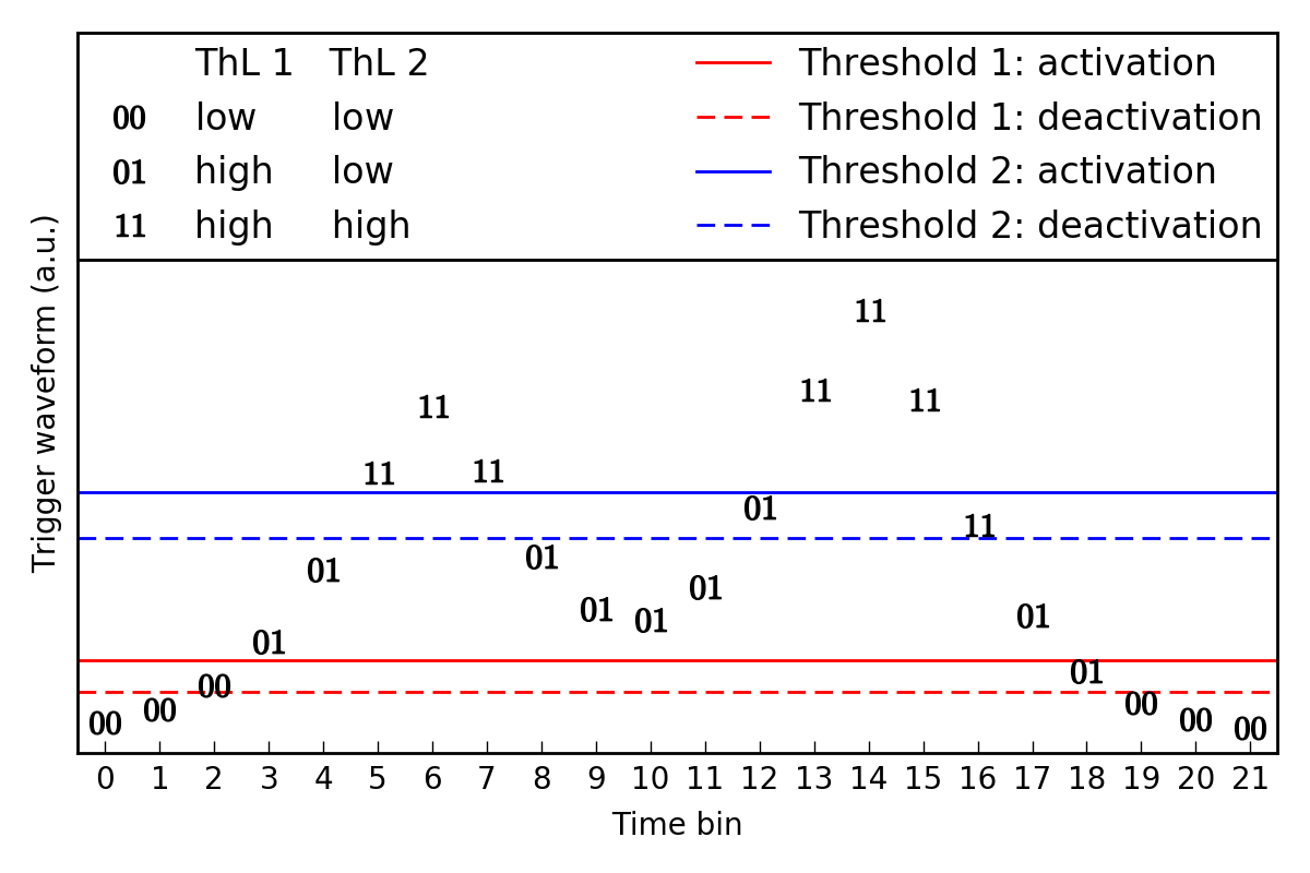
Each submodule is essentially a discriminator with two thresholds to specify when a trigger waveform goes above a threshold in a way that avoids bouncing. The output is used by the Peak Search module to construct a set of trigger primitives, specifically to define the peak search window, report the peak timestamp and peak amplitude, and construct the "trigger word", which is used to make the final L1 trigger decision in the Trigger Logic (TrL) module. There are 8 threshold pairs used in the discriminators: 8 activation thresholds and 8 deactivation thresholds, one for each submodule. This prevents "bouncing", or rapid switching of the outputs between 0 and 1, due to noise in the input. Each of the 8 bits in the output is determined by comparing the input to one Activation/Deactivation threshold pair, one selector, and one previous-output bit. The process for producing an output bit is identical in each submodule and runs in parallel, so we will describe the process for computing only one of the output bits. An example is given in Figure 1 where we have a pileup event (two events which occur very closely in time such that they overlap). We will report on two different ThL submodule results, ThL1 and ThL2, both of which consider this trigger waveform as input. Thus, we will detail both outputs on the figure. The algorithm is as follows:
Figure 1 (below) shows the output of two discriminators for a given trigger waveform input. The markers on the plot show the output bits in each time bin. This is an interesting example because it has two peaks in it. Both ThL1 and ThL2 go above their thresholds at some point, but because of the value of the thresholds, ThL1 goes back down to 0 for a while (reports 2 peaks) while ThL2 stays high for the duration of both peaks. Note the inputs that fall between an activation and deactivation threshold (e.g. time bins 12 and 16) -- the output value then depends on the previous output value. More detailed description (including data transfer information):Step-by-step:
Reset Signal:When the reset input is asserted,
|
| Notes |
|
| Testing Plan |