| Data Input |
There is 1 streaming input, from the Peak Search module with inputs which arrive only when a set of trigger primitives is generated by the PS module.
|
| Configuration and Control Inputs |
Note that the Masks, Selectors, Probabilities, and Enable Bits are set during initialization1 at the start of running and are expected to remain the same after that, but they can be changed at any time if needed. |
| Output |
There is 1 streaming output, which goes to the L1 FIFO.
|
| Error bits |
The module detects and reports several possible erroneous conditions via a register read. The value read out consists of 16 bits; the most-significant bits are unused.
|
| Functionality |
Brief functional description:
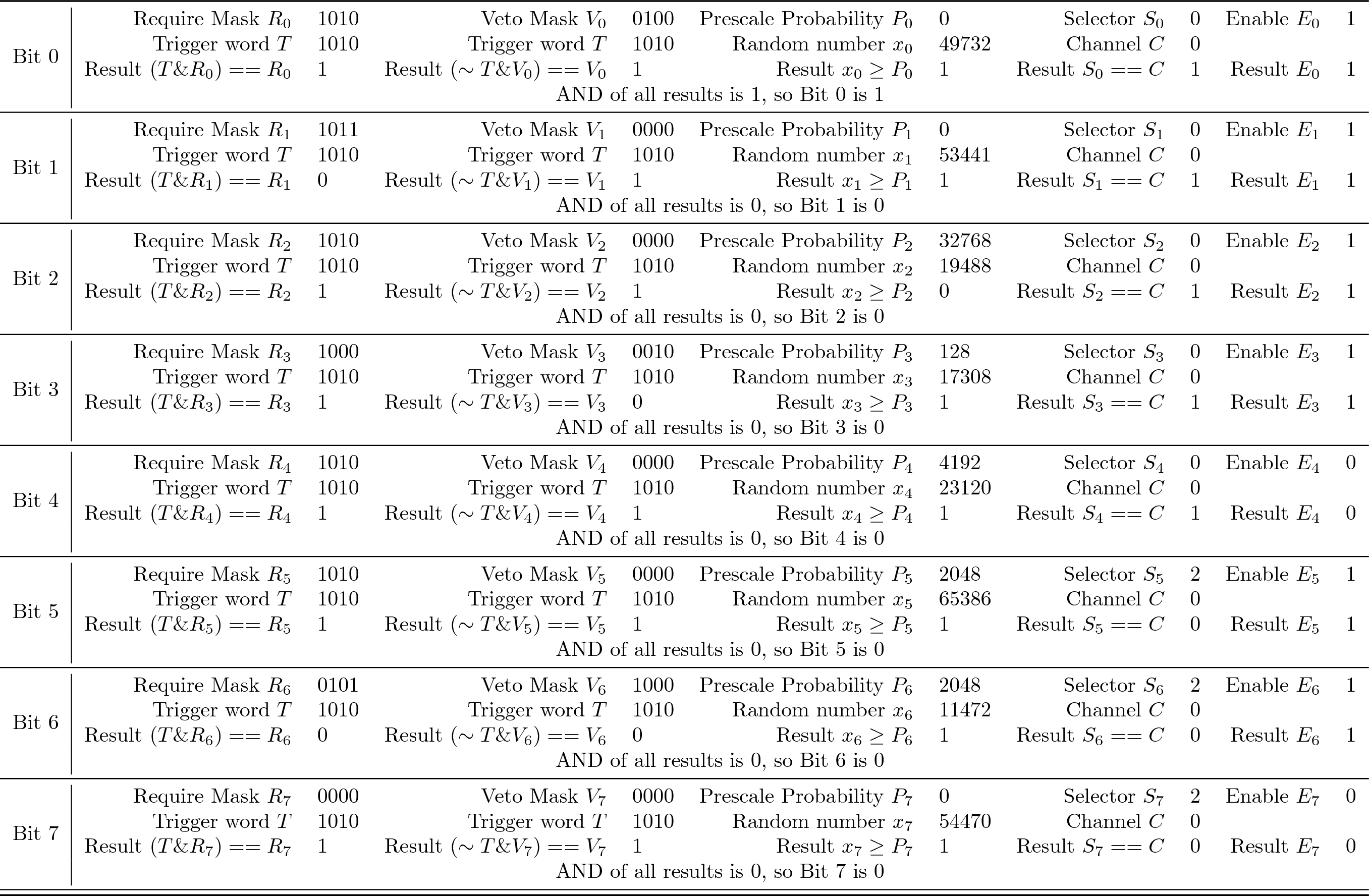
This module makes the L1 trigger decisions based on the 16 bits of the input trigger word. The L1 FIFO will, based on these L1 trigger decisions, record or discard each set of trigger primitives produced by the PS submodules. The trigger primitives produced by the PS modules are passed through this module along with 8 additional bits (the "trigger logic bits"), which are computed by this module. These 8 trigger logic bits represent the L1 trigger decision. That is, the L1 FIFO will record the trigger primitives (including the 8 trigger logic bits) if any of the 8 trigger logic bits is TRUE. This module makes the trigger decision by using 8 pairs of 16-bit bitmasks: a "Require Mask" \(R_i\) (to define which bits of the trigger word are required to be 1) and a "Veto Mask" \(V_i\) (to define which bits of the trigger word are required to be 0). This module checks each incoming trigger word, making sure that all bits set in the "Require Mask" \(R_i\) are 1 in the trigger word, and that all bits set in the "Veto Mask" \(V_i\) are 0 in the trigger word. This check is repeated 8 times, once for each mask pair. In addition to this trigger word check, for each mask pair there is a "Trigger Logic Selector" \(S_i\) which selects which of the 4 PS submodules the mask pair is associated with, an "Enable Bit" \(E_i\) that allows the corresponding output bit to be switched off, and a prescale bit which is derived from the comparison of a random number \(x_i\) (which is generated internally in this module) against a threshold \(P_i\) allowing triggers to be rejected probabilistically. Each "Trigger Logic Selector" \(S_i\) is compared with the channel number $C$ associated with the input, yielding a TRUE bit if they are the same and FALSE otherwise. The logical AND of the trigger word check, the Selector check, the Enable Bit, and the prescale bit determines the corresponding bit in the output. The 8 bits are sent to the L1 FIFO, where they are used to determine whether the set of trigger primitives should be stored or discarded. An example of how the TrL module would handle a (simplified) sample input is given in Table 1, where the input trigger word (labeled $T$ in the table) is 1010 and the input channel number is 0, indicating that this input came from PS submodule 0 (which in turn gets its input from FIR submodule 0 and LC submodule 0). Note that we have used a 4 bit example for simplicity, rather than the full 16 bits in the actual trigger firmware. There are 8 rows in the table, one for each of the 8 trigger bits. The columns show how each of the 8 output bits is computed. For our example input, the final result is a 1 for the first bit (Bit 0), and the rest are all 0, but they are 0 for different reasons (discussed in the next paragraph). For Bit 0, the computations (described more mathematically in the Step-by-Step description below) go as follows:
For the other bits, we simply specify why they aren't set to 1 (they fail to trigger). Bit 1 is 0 because one of the bits in the Require Mask (the last bit) is not present in the trigger word. Bit 2 is 0 because of the prescale. Bit 3 is 0 because one of the bits in the Veto Mask (the third bit) is present in the trigger word. Bit 4 is 0 because the Enable Bit is 0 (this trigger bit is disabled). Bit 5 is 0 because the channel number does not match the Selector (it is designed for a different channel). Bit 6 is 0 for multiple reasons: the required bits are not set in the trigger word, the vetoed bits are set in the trigger word, and the channel number does not match the Selector. Bit 7 is also 0 for multiple reasons: the channel number does not match the Selector, and the Enable Bit is 0. More detailed description (including data transfer information):Step-by-step:
Reset Signal:When the reset input is asserted,
|
| Notes |
|
| Testing Plan |