The Instruction for DCRC Calibration and Tests
0 Preparation
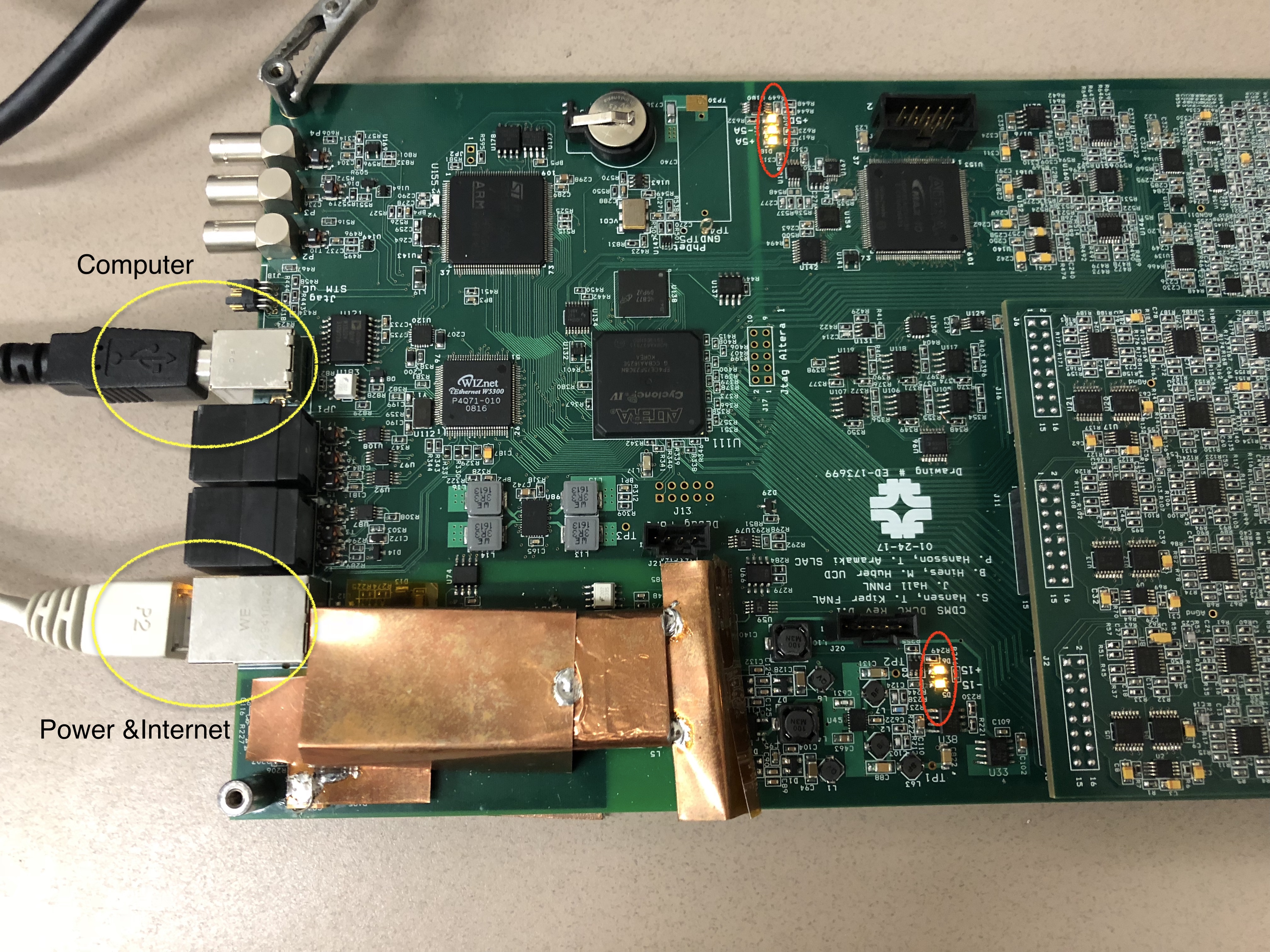
0.0 Check the DCRC LED lights
- Power the DCRC board and connect it to the Computer. Check the 5 LED lights are on.
0.1 Assign/Change an IP address via minicom
- Run the following commands in terminal:
$ minicom -D /dev/ttyUSB0 Ctrl+A +Z (release Ctrl and A before press Z)to show the Menu, then configure minicom(Select O)-->Serial port setup-->change the Hardware Flow Control to No(Select F). Enter to previous menu, then choose Exit.
Check the current IP
Type
SETto check the current IP. (PS: TypeHEfor help. In the list popped out, SOCKET --> SET. )Then assign a new IP address, if applicable.
SET 1 165.91.180.63to reset IP address for the DCRC;SET 2 165.91.180.1to reset the GateWay;SET 3 255.255.254.0to reset the NetMaskNETSAVand thenSETto chekc if new IP address is saved.RESETthe board
Exit minicom with Ctrl+A then X
Disconnect the board
1. Connecting to DCRC
1.0 Prequisite before DAC Calibration and Tests
Download the iphython git package.
Go the directory you'd like to download the git package.
$ git clone ssh://nero.stanford.edu:26/data/git/DCRC/RevD_testbench.git$ cd RevD_testbench/$ git branch -av #Check which branch you are currently in$ git checkout --track origin/feature/jsw_DCRC_controls #CommentsTips: You could switch between branches you already have by the following commands as an example.
$ git branch -av #Check which branch you are currently in$ git checkout master #Switch to another branch 'master'$ git branch -av$ git checkout feature/jsw_DCRC_controls #Switch to branch 'jsw_DCRC_controls'There are two methods you can use to connect to DCRC. 1.1 is remommended
1.1 with ipython notebook(recommended)
The code is included in the git package, what you need to do is to run these lines or the cell contains these lines. Don't forget to change the IP address and port number with yours.
DCRC = DCRC_controls.DCRC('165.91.180.63', 5001) # Four port numbers available: 5000, 5001, 5002, 5003. If one is used pick another. DCRC.open() #Connect to the DCRC1.2 with telnet
In terminal run the following commands,
$ telnet IPAddress.or.HostName PortNumber
Change IPAddress.or.Host and PortNumber to yours. Tpye q and enter to Exit
Necessary Materials for Calibration and Tests:
- DCRC Checklist and Calibrations Spreadsheet
- DCRC Register Map
- DCRC Test Bench (python notebook) (Done in "1.0 Prequisite before DAC Calibration and Tests")
- Oscilloscope and Function generator. (Both included in picoscope.)
- Multimeter
- DCRC Schematics
- DCRCRevD.1 probe points
2. Calibration
2.1 Purposes
Check the slopes and find the offsets, and their uncertainties.
Slopes:
- Driver Offset, LockPoint, SqdBias, QOffset: 0.125 mV/step
- DDSMagnitude: 1.85mV/step
- QETBias: 0.0825 mV/step (measured at miniBob with the 100k resistor)
- QBias: 0.42725 mV/step
- LEDMagnitude: 0.094mV/step (though this one is not as strict because it's a bit different, but also, nobody really will calibrate on LED luminosity...)
2.2 Procedure
- Run the code
- when you see the below code cell and you are ready to run, make sure keep the probe of picoscope in contact with the pin you are going to measure, and connect the probe's ground to an analog ground (AGND), like the picture below showed.
%%timepoints = 0x8000 + array([-0x800, -0x400, -0x200, -0x100, -0x80, -0x40, -0x10, -0x5, 0, 0x5, 0x10, 0x40, 0x80, 0x100, 0x200, 0x400, 0x800])results = array([cal_point(0x760, p, 5, DCRC, scope) for p in points])print(results.shape)print(results)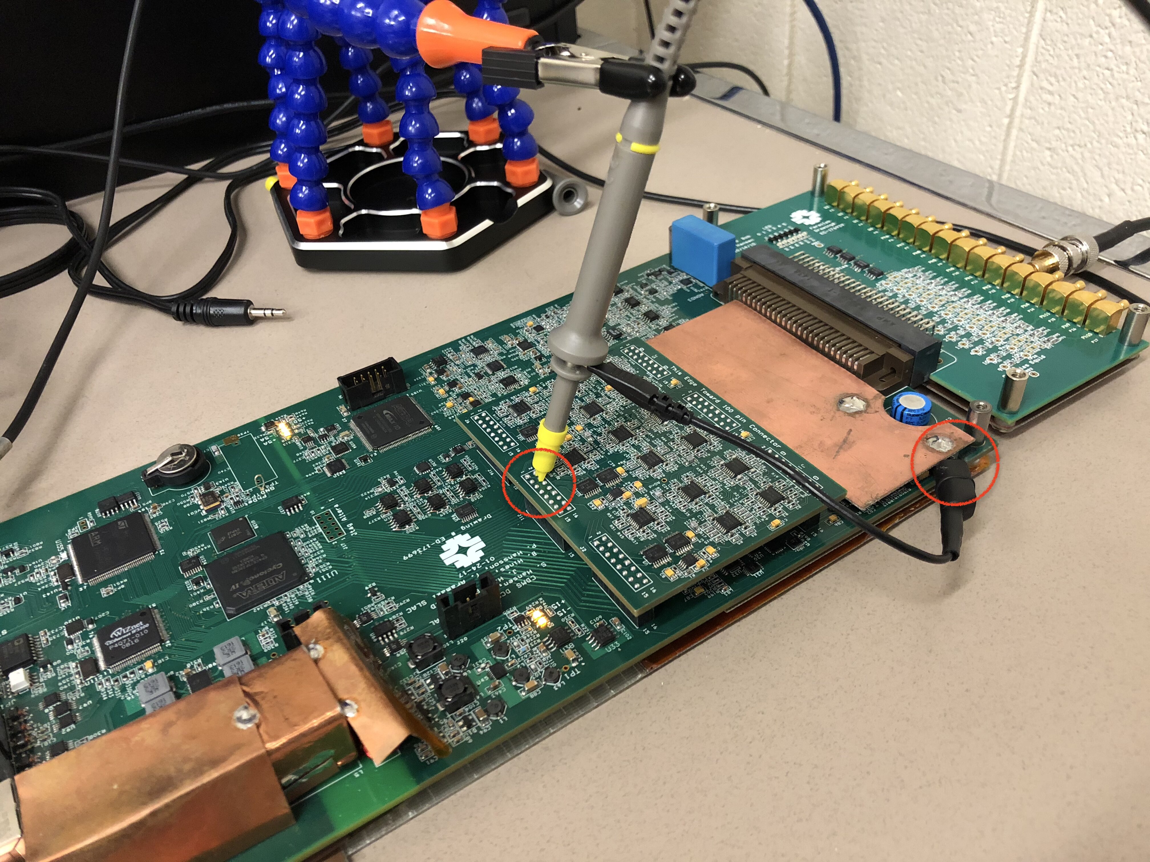
The slope and offset, and their uncertainties, for each pin will be calculated by the code. Fill these values in the calibration sheet. Here is the values you will find in the code.

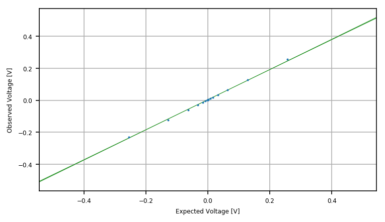
At the end of the code you will see the plot of Measured Values vs Expected Values. Visual Check: ALL the datapoints should follow the fitting line.
- Repeat the above steps for the other pins. Don't forget to change the register (
0x760inresults = array([cal_point(0x760, p, 5, DCRC, scope) for p in points])) when you are ready to calibrate another pin.
3. Tests (Noise, Phonon, Charge and Trigger)
- Run these python files, DCRC Noise Performance.ipynb, DCRC Phonon Signal Test.ipynb and DCRC Charge Signal test.ipynb, to test the noise, phonon and charge seperately.
- Check if the plots show the expected results
3.1 Noise Performance
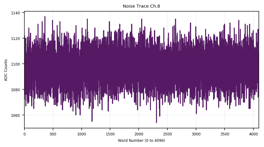
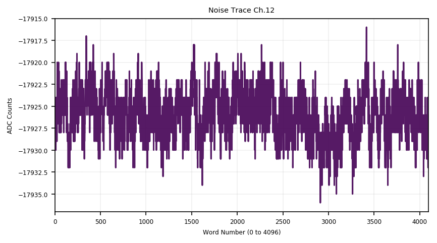
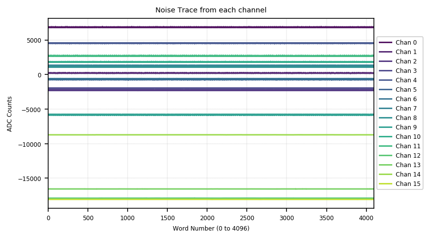
Test the noise performance for ALL channels. Channel 0~11 are phonon channels and Channel 12~15 are charge channels. When you run the code, it will show the traces and PSDs of all channels. Check them visually.
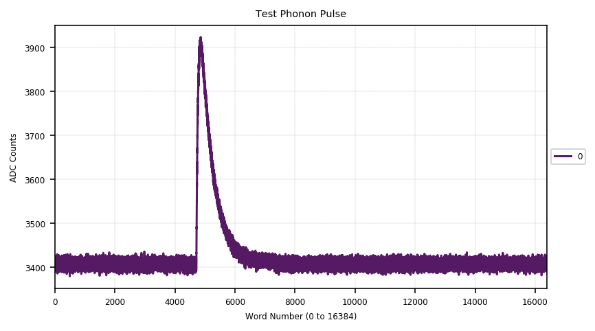
- Check the Trace visually. There should be just random noise and no signals of some specific pattern. The first one is an example of the noise trace for a phonon channel; the second one is for an charge channel; the third one includes the traces of all channels.
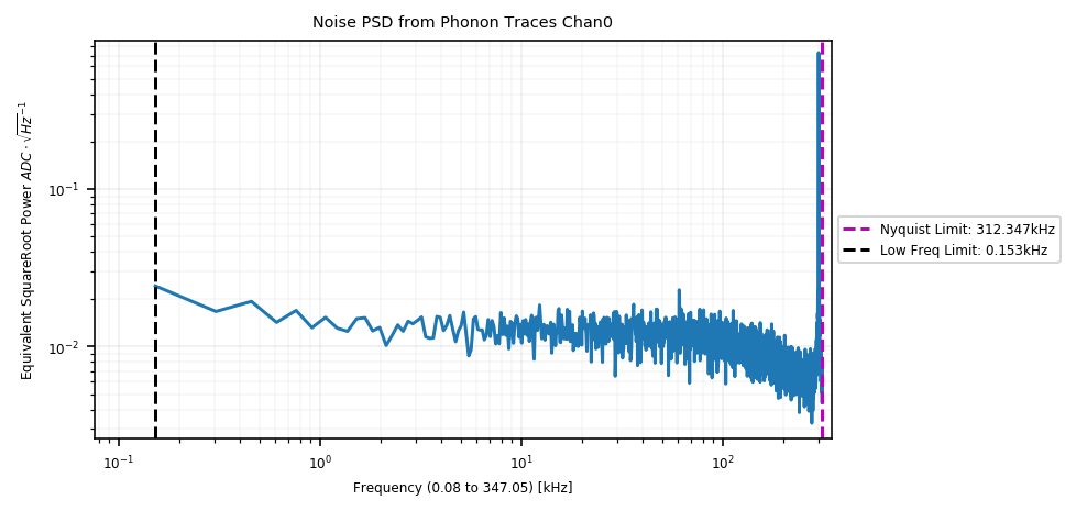
- Check the PSD
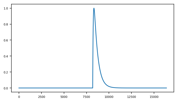
3.2 Phonon Tests
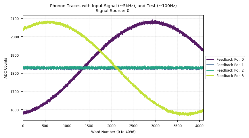
- Check both the Test Signal (signal generator inside DCRC, low frequency) and the Input Signal (produced by picoscope, high frequency) work.

Check Feedback Polarity with difference soruces for each phonon channel. Src 0 is Test Signal and Src 1 is Test Signal + Input Signal.
- Signal Source 0: Trace with Pol 0 and Trace with Pol 3 should have the same shape as well as the same amplitude with a phase difference. Traces with Pol 1 and Pol 2 should be flat.
- Signal Source 1: 'Signal Source 0' + signal of high frequency which is the input signal.

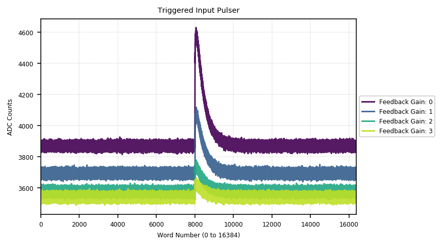
- Check the Feedback Gain for every phonon channel. The amplitudes of the sine waves with low frequency should be ×1, ×2, ×4, ×8 with Feedback Gain 0, 1, 2, 3. Compare the baselines and amplitudes of the sine waves with Dgain0 and Dgain1, the values should be ×1, ×2. Note that there should be no change for the sine waves with high frequncy.


- Trigger Test


The baseline of the pulses shift ???
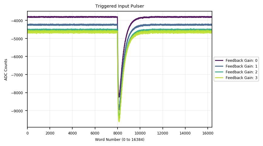
The amplitudes of the pulses are reduced to ×1, ×1/2, ×1/4, ×1/8.
3.3 Charge Test
Similar to the procedure except for "I. Trigger from Charge Pulser". Will be added after the we are happy with "3.2 Phonon Test"
Here is the sample results from previous tests.